| The following procedure outlines the installation of the Kenton MIDI retrofit for the moog memorymoog synthesizer. These instructions are not meant to be a substitute for the Kenton installation instructions, but as clarification. I am not responsible for the accuracy of the information contained here within, nor damages resulting from the use or misuse of this information.
[Click on each picture for a larger more detailed image.] I found it easiest to first solder all connections from the Kenton analog board. Start by soldering the blue and orange power leads to the memorymoog common analog board. The blue lead is connected to the pad at pin 4 of IC U9, an 8 pin DIP package 4558 op amp. The orange lead is connected to the pad at pin 8 of the same IC. Next solder the green lead to the junction pad of resistors R78, R76, and R77. The yellow pitch bend lead 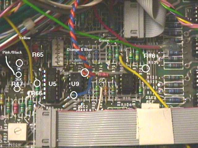 is a little trickier. You will need to note the resistance of R65. If the resistor is 560k ohms [Green-Blue-Yellow-Gold], you will need to solder a 750k ohm resistor in series with the yellow lead before connecting it to the pad at the junction of resistors R65 and R66, directly left of IC U5, a CEM3360. Otherwise, if R65 is 24k ohms [Red-Yellow-Orange-Gold], or a 560k ohm resistor in parallel with a 27k ohm [Red-Purple-Orange-Gold] resistor, directly solder the yellow lead to the pad at the junction of R65 and R66. The pink/black wire connection is trickier yet. Carefully remove 39k ohm resistor R47 [Orange-White-Yellow-Gold]. Solder one end of the included 3k ohm resistor to the rear pad where R47 formerly resided, and one end of the included 36k ohm resistor to the front. Solder the cathode of the included schottky diode to the junction of the 3k ohm and 36k ohm resistors. Finally, solder the pink/black wire to the anode of the diode (marked with a black line) and heatshrink the connection. is a little trickier. You will need to note the resistance of R65. If the resistor is 560k ohms [Green-Blue-Yellow-Gold], you will need to solder a 750k ohm resistor in series with the yellow lead before connecting it to the pad at the junction of resistors R65 and R66, directly left of IC U5, a CEM3360. Otherwise, if R65 is 24k ohms [Red-Yellow-Orange-Gold], or a 560k ohm resistor in parallel with a 27k ohm [Red-Purple-Orange-Gold] resistor, directly solder the yellow lead to the pad at the junction of R65 and R66. The pink/black wire connection is trickier yet. Carefully remove 39k ohm resistor R47 [Orange-White-Yellow-Gold]. Solder one end of the included 3k ohm resistor to the rear pad where R47 formerly resided, and one end of the included 36k ohm resistor to the front. Solder the cathode of the included schottky diode to the junction of the 3k ohm and 36k ohm resistors. Finally, solder the pink/black wire to the anode of the diode (marked with a black line) and heatshrink the connection.
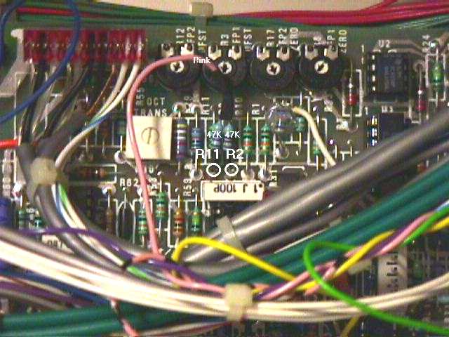 The foot controller inputs are also found on the memorymoog common analog board, towards the left rear. Slide a short piece of heatshrink over the end of the pink wire, then solder the two included 47k ohm resistors in a Y, and slide the heatshrink over the joint. Locate 5.6M ohm resistors R2 and R11 [Green-Purple-Green-Gold] and solder the other end of one 47k ohm resistor to R2 (the end away from the trim pot) and the other 47k ohm resistor to R11.
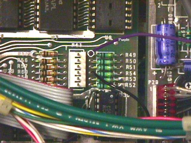 The sustain pedal connection is found on the far right of memorymoog digital logic board near connector P41. Solder the purple lead from the Kenton analog board to the left side of R49, a 100k ohm [Brown-Black-Yellow-Gold] resistor. The sustain pedal connection is found on the far right of memorymoog digital logic board near connector P41. Solder the purple lead from the Kenton analog board to the left side of R49, a 100k ohm [Brown-Black-Yellow-Gold] resistor.
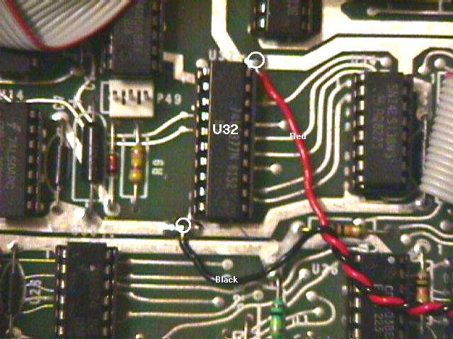 The next two connections to the memorymoog digital board is for +5 volt power. Connect the red lead of the included power harness to the pad at pin 20 of U32, a 74LS377 address latch. Connect the black lead to the pad at pin 10 of the same IC. The next two connections to the memorymoog digital board is for +5 volt power. Connect the red lead of the included power harness to the pad at pin 20 of U32, a 74LS377 address latch. Connect the black lead to the pad at pin 10 of the same IC.
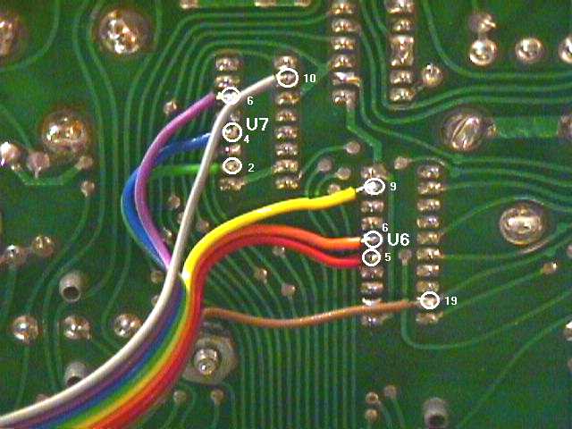 The connections for the program select harness can be a little tricky. The program select harness is an eight conductor ribbon cable [Brown to Grey] with a ten pin connector on one end. These connetions are made on the solder side of the memorymoog LSC (front panel) board. Carefully locate IC U7 to the right of the numeric keypad. Note the mounting nut directly below the IC. Solder the grey wire as shown in the picture, followed by the violet, blue, and green wires. Next locate IC U6 to the lower right of IC U7. Connect the yellow, orange, red, and brown wires as shown. The connections for the program select harness can be a little tricky. The program select harness is an eight conductor ribbon cable [Brown to Grey] with a ten pin connector on one end. These connetions are made on the solder side of the memorymoog LSC (front panel) board. Carefully locate IC U7 to the right of the numeric keypad. Note the mounting nut directly below the IC. Solder the grey wire as shown in the picture, followed by the violet, blue, and green wires. Next locate IC U6 to the lower right of IC U7. Connect the yellow, orange, red, and brown wires as shown.
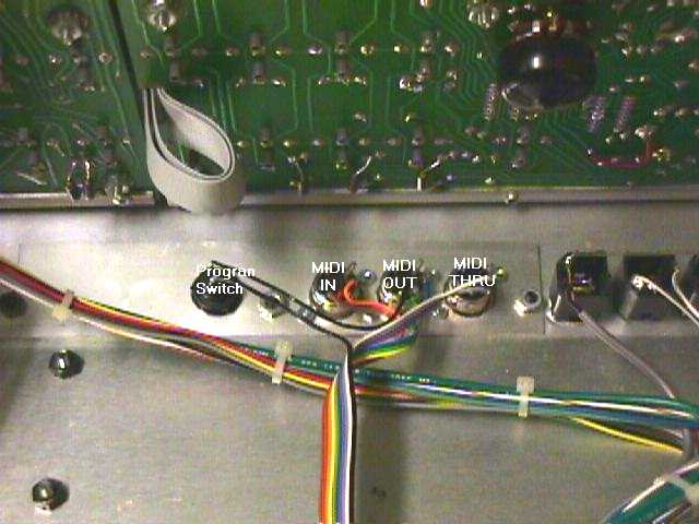 Drill and mount the 5 pin DIN jacks and momentary switch on the aluminum filler panel on the rear of the memorymoog. I positioned the MIDI in to the left of the MIDI out and thru, similar to Roland and other synthesizer manufacturers. I also chose to use a low profile momentary switch [Radio Shack part number 275-644] as opposed to the switch included in the kit. Drill and mount the 5 pin DIN jacks and momentary switch on the aluminum filler panel on the rear of the memorymoog. I positioned the MIDI in to the left of the MIDI out and thru, similar to Roland and other synthesizer manufacturers. I also chose to use a low profile momentary switch [Radio Shack part number 275-644] as opposed to the switch included in the kit.
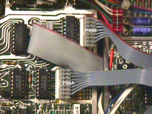 Remove the keyboard cable from the keyboard and connectors P48A and P48B located on the memorymoog digital logic board. Connect the included 16 conductor ribbon cable to the memorymoog keyboard. Next locate connector P48B on the right side of the memorymoog digital logic board. Connect the striped eight conductor split of the interconnect cable, ensuring the red stripe is connected to pin 1 towards the rear of the unit. Connect the other eight conductor split to connector P48A. Remove the keyboard cable from the keyboard and connectors P48A and P48B located on the memorymoog digital logic board. Connect the included 16 conductor ribbon cable to the memorymoog keyboard. Next locate connector P48B on the right side of the memorymoog digital logic board. Connect the striped eight conductor split of the interconnect cable, ensuring the red stripe is connected to pin 1 towards the rear of the unit. Connect the other eight conductor split to connector P48A.
The recommended location of the Kenton digital and analog boards requires drilling the chassis and reforming keyboard brackets, so I chose a new 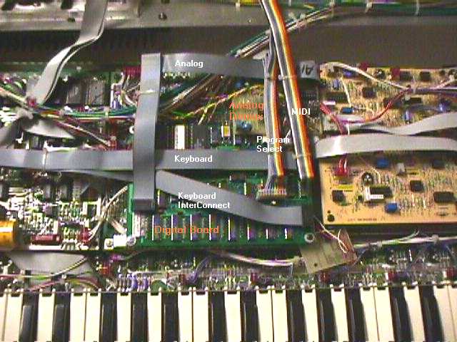 location to mount the boards. I formed a small Z bracket from aluminum, and mounted the Kenton digital board above the memorymoog common analog board. I mounted the Kenton analog board on a stand-off towards the rear of the memorymoog common analog board. I insulated the back side of the Kenton boards with a thin piece of non-conductive plastic. I recommend using Kenton's suggested mounting locations and included hardware, unless you feel comfortable doing otherwise. Once you have mounted the Kenton boards, connect the keyboard, keyboard interconnect, analog demux, and power cables as outlined in the Kenton instructions. Fire up the synth and enjoy. location to mount the boards. I formed a small Z bracket from aluminum, and mounted the Kenton digital board above the memorymoog common analog board. I mounted the Kenton analog board on a stand-off towards the rear of the memorymoog common analog board. I insulated the back side of the Kenton boards with a thin piece of non-conductive plastic. I recommend using Kenton's suggested mounting locations and included hardware, unless you feel comfortable doing otherwise. Once you have mounted the Kenton boards, connect the keyboard, keyboard interconnect, analog demux, and power cables as outlined in the Kenton instructions. Fire up the synth and enjoy.
|
||||